Hey there! To learn a protocol, always asks how it works. Always remember, protocol is a set of procedures or set of rules. In ospf, there are actually 7 process or steps to achieve neighbor adjacency. Let us first enumerate those processes.
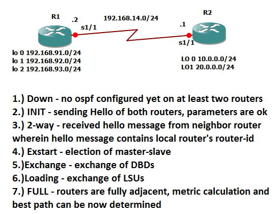
1.) Down
2.) INIT
3) 2-way
4.) Exstart
5.) Exhange
6.) Loading
7.) Full
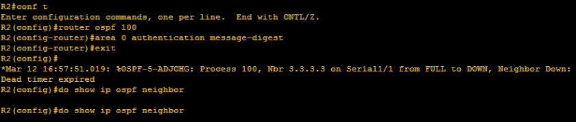
1.) DOWN- There will be only two reasons why an ospf network would go down
a.)When an interface is configured with an stafic ospf neighbor
- this will be topic which is covered on CCNP – route wherein instead that a hello message is sent to a multicast address, it will be sent to just unicast address
b.) When hello timer expires and then dead timer takes place.
For us to easily understand, those timers and multicast address that I am telling you. We will discuss first hello message content and its timer.
Hello Message Contents:
1.) Router-ID of local router- router-id of the router which will send hello message
2.) Area-ID- area id of the interface of the local router
3.) Address & Subnet Mask – address & subnet mask of the interface
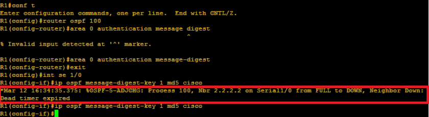
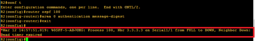
4.) Authentication type- the password or passive interface configured on the router interface
5.) Hello & Dead Interval – there dyou go!- Hello and dead interval are check alive timers. Hello interval is a message sent by local router to check if neighbor routers are still alive. If neighbor routers did not response after the default value of 10 seconds, it will wait for 40 seconds for it to declare that the neighbor is officially down. Please take note that 40 seconds is just the default value of ospf dead timer. The values can be also configured.
6.) Router interface priority – likewise I mentioned on the previous blog, priority is used on election of master-slave router. We will further discuss this as we go on, but just to give you a hint, priority value is used who will be the first router to send its LSDB
7.) DR & BDR information – let us make it simple, these can be compared to the master-slave routers. DR stands for designated router and BDR stands for back-up designated router. We will dig deeper on this on the next blog pages
8.) Router-ID of the local router’s neighbor – this appears on the neighbor table of the local router
Alright so those are the contents of the hello message which will be sent by the local router to the neighbor router and also the local router should expect those information to be sent by neighbor router to him.
Always remember mate, that there can be multiple protocols which also sends information like hello message or its counterpart. So, the question is how will a router knows that the hello message is supposed to be sent to him.

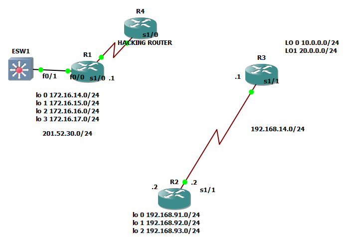
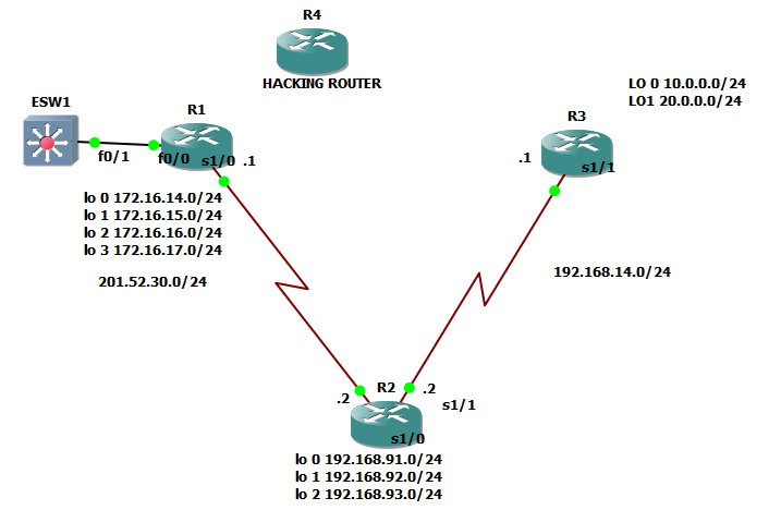
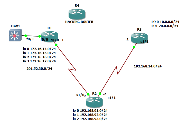
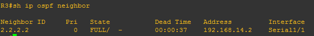
On the image above, the question is how will neighbor router will know that it is that he is the recipient of the hello message? Also how will R3 would know that since EIGRP is configured to him, he is not recipient of the hello message? The message is sent with destination address of 224.0.0.5 which is a multicast address. I mean to say that the hello message is broadcast to the network but intended only to the group of routers that run OSPF protocol.
Let us say that R3 drops the packet since he is not the recipient of the hello message and R1, the neighbor router received the hello message of R2. What will happen next?
R1 will counter check the hello sent by R2. And the following should match:
1.) Area ID – if R1 is on area 0, R2 must be also on area 0
2.) Area type – we will discuss this further but just to give you a hint these are normal, stubby, not so stubby area., sounds very complex but we will discuss this as we go on
3.)Network address & Submet mask
4.) Hello & Dead intervals
5.) Authentication information
6.)Router-ID must be unique
***********************************************************************
OSPF STAGE 2: INIT
How we will transition from DOWN state to INIT ?
Here’s how it goes! Let play a scenario wherein R1 and R2 is trying to establish neighbor adjacency
Step1 ospf interface of R1 got activated, R1 will create its own LSA, remember LSA? HEHE, R1 will send hello message to its neighbor but since no neighbor routers got ospf activated, hello timer will expire and will proceed to dead timer.
Step2 ospf interface of R2 once got activated,R2 will create its own LSA, R2 will send hello to R1. (
Step3 R1 will counter check the hello message sent of R2
Step 4 once all the parameters are achieved, R1 will add R2 as its neighbor and then the OSPF process will transition from DOWN to INIT, so let us define INIT stage
INIT STAGE – is when all hello parameters are and then the neighbor router is added on neighbor table of R1, it will remain on INIT stage until it received a hello with its own router-ID. Sound confusing? we will explain that further as we transition to 2-way
Step 5 – Since R1 already added R2 as its own neighbor, R1 will send hello message once again to R2 with hello message wherein the neighbor is R2. Since the hello message has R2’s router-id which will be sent to R2, therefore it is now the time to transition to 2-WAY
***********************************************************************
2-WAY –> If a router received a hello from a neighbor and sees its own router-id
is included in the list of neighbor
Step 6
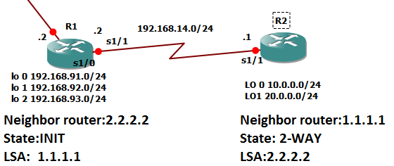
Let us have a recap from step 5, since R1 is on INIT state and sent hello to R2 with its neighbor router-id as hello content, R2 will add R1 as its neighbor router and will skip to 2-way, Step 6 would be R2 will send hello to R1 with its R1’s router-id as hello content then R1 will transition to 2-WAY. Once both routers are on 2-way state, it will transition to EXSTART
***********************************************************************
EXSTART – the process of election on routers who will send its DBD
DBD – database descriptor – summary of router-ids of all LSAs inside LSDB
Step 7 Election will be on master-slave process
Master- highest router -id
Slave – lowest router-id
***********************************************************************
EXCHANGE – when we already figured out the master and the slave among routers.
Step 8 On our case, R2 will be the one who will send DBDs. R1 will just confirm that R1 & R2 share the same DBD as a reply ro R2
***********************************************************************
LOADING – it is the process of checking the LSDB of those routers involved to verify that they share the same LSDB
Step 9 After exchange of DBDs , if there are some neighbor information that they missed, master router will send a link state request which will lead to link state update and link state acknowledgment. Here’s how it goes!
Let’s say:
R2 ( master) : hi R1 here is my ospf database
R1 ( slave) : Got it master! I will try to counter-check and double check it!
Let’s say R2 has a new network configured to its interface and that network will be 10.0.21.0/24
R1 ( slave): R2 ( master ) , it seems like I don’t have yet the new network 10.0.21.0/24 configured to your interface, can I request to have that one . – THIS IS WHAT WE CALL LINK STATE REQUEST
R2( master) : Ohh oaah! I missed to inform you that, ok no worries, I will provide you that network as LINK STATE UPDATE
R1( slave): Thank you so much master, I hope that you consider this one as LINK STATE ACKNOWLEGMENT to inform you that I already received the new neighbor information that you got.
***********************************************************************
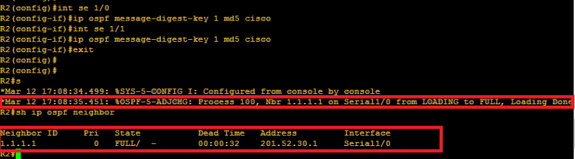
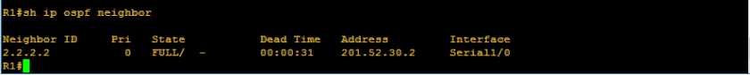
FULL- we are now done with the final OSPF process wherein we have full neighbor adjacency. Loading state will be finished if all the routers have the same LSDB
***********************************************************************
Just a quick summary of OSPF process!
Oh yeah! Apologies if it is very lengthy and boring but I hope that I was able to educate you today!