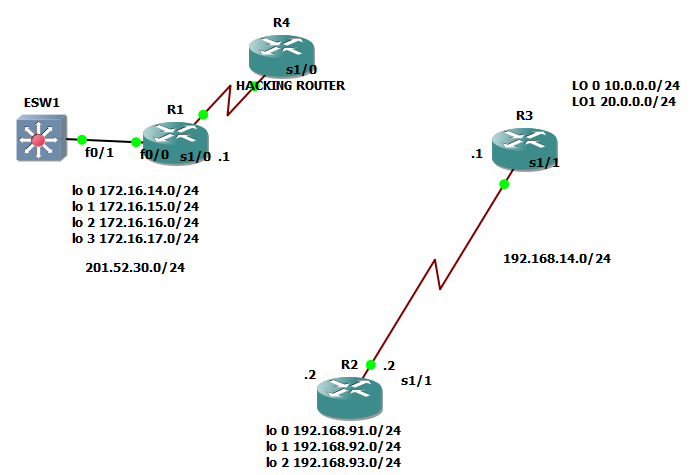
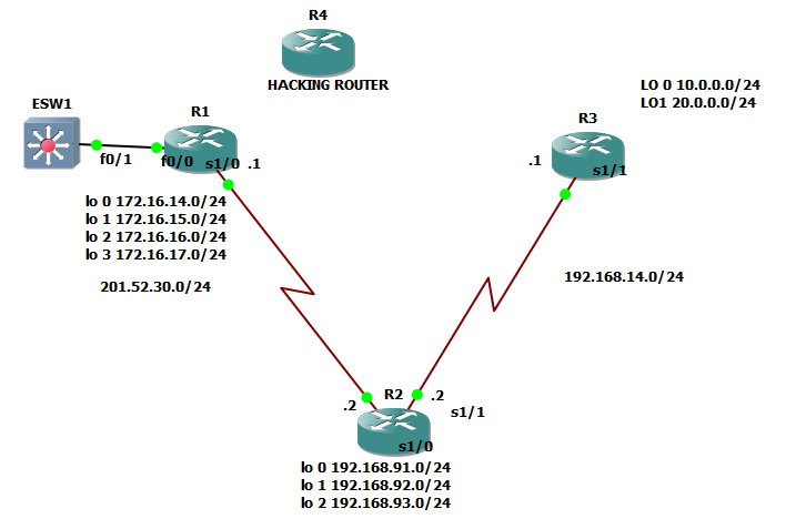
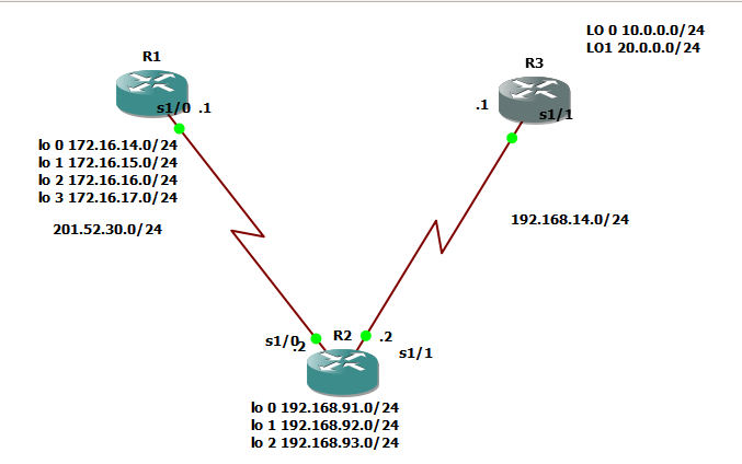
Good morning! We’ll proceed with static routing with the network topology below:
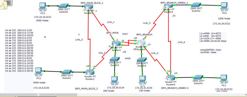
The primary configurations are below:
@ BPO_MAIN_BLDG_1
enable
conf t
line console 0
password cisco
logging sync
exec-timeout 20 30
login
exit
line vty 0 15
password cisco
logging sync
exec-timeout 20 30
login
exit
hostname BPO_MAIN_BLDG_1
enable secret class
service password-encryption
no ip domain-lookup
banner motd “AUTHORIZED ACCESS ONLY”
do wr
@BPO_MAIN_BLDG_2
enable
conf t
line console 0
password cisco
logging sync
exec-timeout 20 30
login
exit
line vty 0 15
password cisco
logging sync
exec-timeout 20 30
login
exit
hostname BPO_MAIN_BLDG_2
enable secret class
service password-encryption
no ip domain-lookup
banner motd “AUTHORIZED ACCESS ONLY”
do wr
@BPO_MAIN
enable
conf t
line console 0
password cisco
logging sync
exec-timeout 20 30
login
exit
line vty 0 15
password cisco
logging sync
exec-timeout 20 30
login
exit
hostname BPO_MAIN
enable secret class
service password-encryption
no ip domain-lookup
banner motd “AUTHORIZED ACCESS ONLY”
do wr
@BPO_BRANCH
enable
conf t
line console 0
password cisco
logging sync
exec-timeout 20 30
login
exit
line vty 0 15
password cisco
logging sync
exec-timeout 20 30
login
exit
hostname BPO_BRANCH
enable secret class
service password-encryption
no ip domain-lookup
banner motd “AUTHORIZED ACCESS ONLY”
do wr
@BPO_BRANCH_ANNEX_1
enable
conf t
line console 0
password cisco
logging sync
exec-timeout 20 30
login
exit
line vty 0 15
password cisco
logging sync
exec-timeout 20 30
login
exit
hostname BPO_BRANCH_ANNEX_1
enable secret class
service password-encryption
no ip domain-lookup
banner motd “AUTHORIZED ACCESS ONLY”
do wr
@BPO_BRANCH_ANNEX-2
enable
conf t
line console 0
password cisco
logging sync
exec-timeout 20 30
login
exit
line vty 0 15
password cisco
logging sync
exec-timeout 20 30
login
exit
hostname BPO_BRANCH_ANNEX-2
enable secret class
service password-encryption
no ip domain-lookup
banner motd “AUTHORIZED ACCESS ONLY”
do wr
***************************
@ main bldg 1
en
conf t
int se 3/0
ip add 200.0.0.1 255.255.255.252
no shut
exit
int se 2/0
ip address 200.0.0.17 255.255.255.252
no shut
exit
@main bldg 2
en
conf t
int se 2/0
ip add 200.0.0.18 255.255.255.252
shut
no shut
exit
int se 3/0
ip add 200.0.0.5 255.255.255.252
shut
no shut
exit
@ BPO_MAIN
en
conf t
int se 6/0
ip add 200.0.0.2 255.255.255.252
no shut
exit
int se 7/0
ip add 200.0.0.6 255.255.255.252
no shut
exit
int se 2/0
ip add 200.0.0.25 255.255.255.252
no shut
exit
int se 3/0
ip add 200.0.0.29 255.255.255.252
no shut
exit
int fa 0/0
no shut
exit
@ BPO_BRANCH
en
conf t
int se 2/0
ip add 200.0.0.26 255.255.255.252
no shut
exit
int se 3/0
ip add 200.0.0.30 255.255.255.252
no shut
exit
int se 6/0
ip add 200.0.0.9 255.255.255.252
no shut
exit
int se 7/0
ip add 200.0.0.13 255.255.255.252
no shut
exit
int fa 0/0
no shut
exit
@bpo annex 1
en
conf t
int se 2/0
ip add 200.0.0.10 255.255.255.252
no shut
exit
int se 3/0
ip add 200.0.0.21 255.255.255.252
no shut
exit
int gigabitEthernet7/0
no shut
exit
@bpo annex 2
en
conf t
int se 2/0
ip add 200.0.0.14 255.255.255.252
no shut
exit
int se 3/0
ip add 200.0.0.22 255.255.255.252
no shut
exit
int gigabitEthernet 8/0
no shut
exit
**********************************************************************
Game!
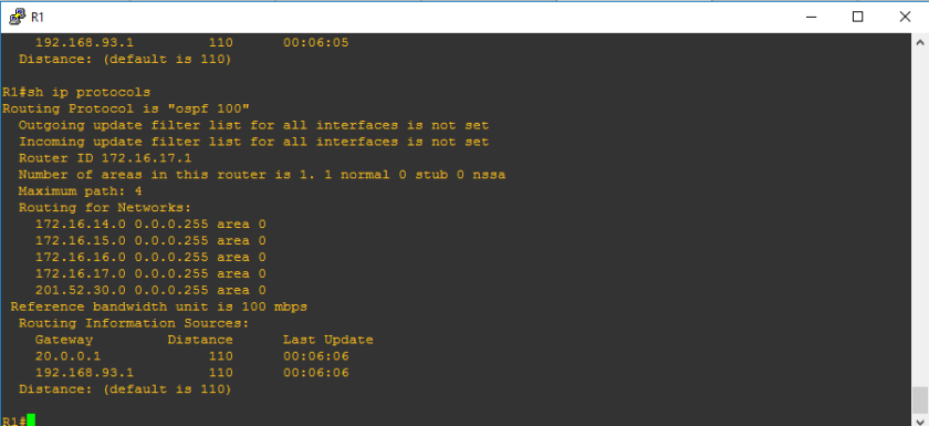
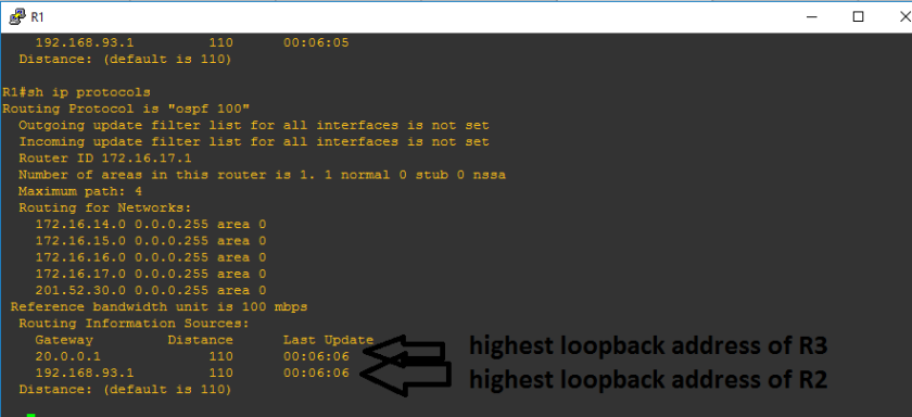
Let us verify:


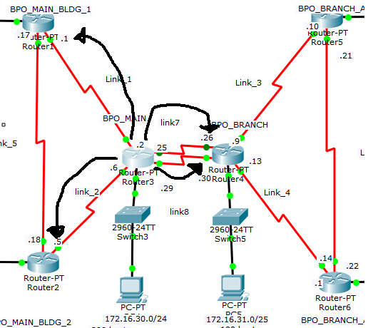
Alright, so we’ll begin the discussion focusing on BPO_MAIN:

BPO_MAIN has next hop IP addresses:
200.0.0.1
200.0.0.5
200.0.0.26
200.0.0.30
which means that succesful ping from BPO_MAIN to those ip addresses can be guaranteed.Let’s verify:


Let us try to get a response from remote network address, let’s say 200.0.0.10 and 200.0.0.13

So an aspiring network engineer, it is our task to provide routing or successful ping on remote network addresses. It is reasonable that we are not going to get a response because those ip addresses are not listed on the routing table of the BPO_MAIN. Let us verify:

We got possible to 200.0.0.1,200.0.0.5,200.0.0.26,200.0.0.30 because it is part of the network which is directly connected. So since we are only limited with those directly connected networks, we can add other ip address so that we can have ping response from BPO_MAIN. There are multiple ways to add it, but let us start first with static routing.
Drawbacks of Static Routing:
1.) In the event of network changes, we must manually configured static routing again
2.) It is not advisable for large networks
3.) It takes time to implement since it is manually configured.
*********************************************************************
Syntax for STATIC route
ip route (network destination) (subnet mask) (next hop ip address)
1.) Network destination is the network address of the route you want to reach
2.)Subnet mask of the network destination
3.) next hop IP address- it is the ip address of the neighbor to which you need to pass the packet to reach the network destination.
Game, let us start configuring static route.
Technique:It may be going to be hard to know the remote network addresses of other routers, because it may require us subnetting techniques, but we can easily know the remote network addresses by making a telnet session to the branch router and make a show ip route to that branch router.

Configuration:
Let us try to reach BPO_MAIN_BLDG_1 first:
en
conf t
ip route 200.0.0.0 255.255.255.252 200.0.0.1
ip route 200.0.0.16 255.255.255.252 200.0.0.1
exit
Let us try to get a ping to 200.0.0.17 and 200.0.0.1

Verify:

There you go! We’ve seen that the network 200.0.0.16 was learned via static configuration by the help of next hop ip address: 200.0.0.1
Let us try to reach BPO_MAIN_BLDG 2
en
conf t
ip route 200.0.0.4 255.255.255.252 200.0.0.5
ip route 200.0.0.16 255.255.255.252 200.0.0.5
exit
Verify:

Check ping:
ping 200.0.0.18
ping 200.0.0.5

Alright, so BPO_MAIN is now reaching the left side of the network . I’ll get back to you once I finished the entire configuration for all the routers.
Yup, I took my breakfast and finally done with the static configuration:
Static Route
@ BPO MAIN
en
conf t
ip route 200.0.0.0 255.255.255.252 200.0.0.1
ip route 200.0.0.16 255.255.255.252 200.0.0.1
exit
en
conf t
ip route 200.0.0.4 255.255.255.252 200.0.0.5
ip route 200.0.0.16 255.255.255.252 200.0.0.5
exit
en
conf t
ip route 200.0.0.8 255.255.255.252 200.0.0.26
ip route 200.0.0.8 255.255.255.252 200.0.0.30
exit
ip route 200.0.0.12 255.255.255.252 200.0.0.26
ip route 200.0.0.12 255.255.255.252 200.0.0.30
exit
conf t
ip route 200.0.0.24 255.255.255.252 200.0.0.26
ip route 200.0.0.28 255.255.255.252 200.0.0.30
exit
conf t
ip route 200.0.0.24 255.255.255.252 200.0.0.30
ip route 200.0.0.28 255.255.255.252 200.0.0.26
exit
conf t
ip route 200.0.0.8 255.255.255.252 200.0.0.26
ip route 200.0.0.20 255.255.255.252 200.0.0.26
exit
conf t
ip route 200.0.0.8 255.255.255.252 200.0.0.30
ip route 200.0.0.20 255.255.255.252 200.0.0.30
exit
@BPO MAIN BLDG 1
conf t
ip route 200.0.0.4 255.255.255.252 200.0.0.18
ip route 200.0.0.16 255.255.255.252 200.0.0.18
exit
conf t
ip route 200.0.0.0 255.255.255.252 200.0.0.2
ip route 200.0.0.14 255.255.255.252 200.0.0.2
ip route 200.0.0.24 255.255.255.252 200.0.0.2
ip route 200.0.0.28 255.255.255.252 200.0.0.2
exit
conf t
ip route 200.0.0.8 255.255.255.252 200.0.0.2
ip route 200.0.0.12 255.255.255.252 200.0.0.2
ip route 200.0.0.24 255.255.255.252 200.0.0.2
ip route 200.0.0.28 255.255.255.252 200.0.0.2
exit
conf t
ip route 200.0.0.8 255.255.255.252 200.0.0.2
ip route 200.0.0.20 255.255.255.252 200.0.0.2
exit
conf t
ip route 200.0.0.12 255.255.255.252 200.0.0.2
ip route 200.0.0.20 255.255.255.252 200.0.0.2
exit
*************************************
@ BPO MAIN BLDG 2
conf t
ip route 200.0.0.0 255.255.255.252 200.0.0.17
ip route 200.0.0.16 255.255.255.252 200.0.0.7
exit
conf t
ip route 200.0.0.0 255.255.255.252 200.0.0.6
ip route 200.0.0.4 255.255.255.252 200.0.0.6
ip route 200.0.0.24 255.255.255.252 200.0.0.6
ip route 200.0.0.28 255.255.255.252 200.0.0.6
exit
conf t
ip route 200.0.0.8 255.255.255.252 200.0.0.6
ip route 200.0.0.12 255.255.255.252 200.0.0.6
ip route 200.0.0.24 255.255.255.252 200.0.0.6
ip route 200.0.0.28 255.255.255.252 200.0.0.6
exit
conf t
ip route 200.0.0.8 255.255.255.252 200.0.0.6
ip route 200.0.0.20 255.255.255.252 200.0.0.6
exit
conf t
ip route 200.0.0.12 255.255.255.252 200.0.0.6
ip route 200.0.0.20 255.255.255.252 200.0.0.6
exit
******************************************
@ BPO branch
conf t
ip route 200.0.0.8 255.255.255.252 200.0.0.10
ip route 200.0.0.20 255.255.255.252 200.0.0.10
exit
conf t
ip route 200.0.0.12 255.255.255.252 200.0.0.14
ip route 200.0.0.20 255.255.255.252 200.0.0.14
exit
conf t
ip route 200.0.0.0 255.255.255.252 200.0.0.25
ip route 200.0.0.4 255.255.255.252 200.0.0.25
ip route 200.0.0.24 255.255.255.252 200.0.0.25
ip route 200.0.0.28 255.255.255.252 200.0.0.25
ip route 200.0.0.0 255.255.255.252 200.0.0.29
ip route 200.0.0.4255.255.255.252 200.0.0.29
ip route 200.0.0.24 255.255.255.252 200.0.0.29
ip route 200.0.0.28 255.255.255.252 200.0.0.29
exit
conf t
ip route 200.0.0.0 255.255.255.252 200.0.0.25
ip route 200.0.0.16 255.255.255.252 200.0.0.25
ip route 200.0.0.0 255.255.255.252 200.0.0.29
ip route 200.0.0.16 255.255.255.252 200.0.0.29
exit
conf t
ip route 200.0.0.4 255.255.255.252 200.0.0.25
ip route 200.0.0.16 255.255.255.252 200.0.0.25
ip route 200.0.0.4 255.255.255.252 200.0.0.29
ip route 200.0.0.16 255.255.255.252 200.0.0.29
exit
*********************
@ ANNEX 1
conf t
ip route 200.0.0.8 255.255.255.252 200.0.0.9
ip route 200.0.0.12 255.255.255.252 200.0.0.9
ip route 200.0.0.24 255.255.255.252 200.0.0.9
ip route 200.0.0.28 255.255.255.252 200.0.0.9
exit
conf t
ip route 200.0.0.12 255.255.255.252 200.0.0.14
ip route 200.0.0.20 255.255.255.252 200.0.0.14
exit
conf t
ip route 200.0.0.0 255.255.255.252 200.0.0.9
ip route 200.0.0.4 255.255.255.252 200.0.0.9
ip route 200.0.0.24 255.255.255.252 200.0.0.9
ip route 200.0.0.28 255.255.255.252 200.0.0.9
exit
conf t
ip route 200.0.0.0 255.255.255.252 200.0.0.9
ip route 200.0.0.16 255.255.255.252 200.0.0.9
exit
conf t
ip route 200.0.0.4 255.255.255.252 200.0.0.9
ip route 200.0.0.16 255.255.255.252 200.0.0.9
exit
@ Annex 2
conf t
ip route 200.0.0.8 255.255.255.252 200.0.0.21
ip route 200.0.0.20 255.255.255.252 200.0.0.21
exit
conf t
ip route 200.0.0.8 255.255.255.252 200.0.0.13
ip route 200.0.0.12 255.255.255.252 200.0.0.13
ip route 200.0.0.24 255.255.255.252 200.0.0.13
ip route 200.0.0.28 255.255.255.252 200.0.0.13
exit
conf t
ip route 200.0.0.0 255.255.255.252 200.0.0.13
ip route 200.0.0.4 255.255.255.252 200.0.0.13
ip route 200.0.0.24 255.255.255.252 200.0.0.13
ip route 200.0.0.28 255.255.255.252 200.0.0.13
exit
conf t
ip route 200.0.0.0 255.255.255.252 200.0.0.13
ip route 200.0.0.16 255.255.255.252 200.0.0.13
exit
conf t
ip route 200.0.0.4 255.255.255.252 200.0.0.13
ip route 200.0.0.16 255.255.255.252 200.0.0.13
exit
PING TEST @ BPO MAIN BLDG 1

PING TEST @ BPO MAIN

At last we are getting succesful ping response whether we are on the side or at the middle of the topology.
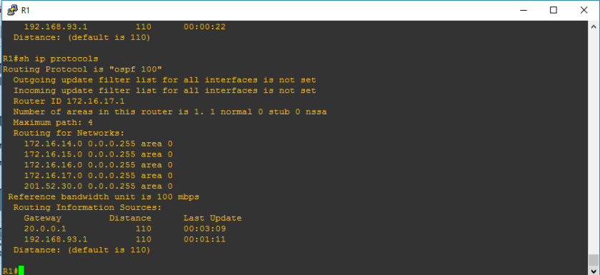
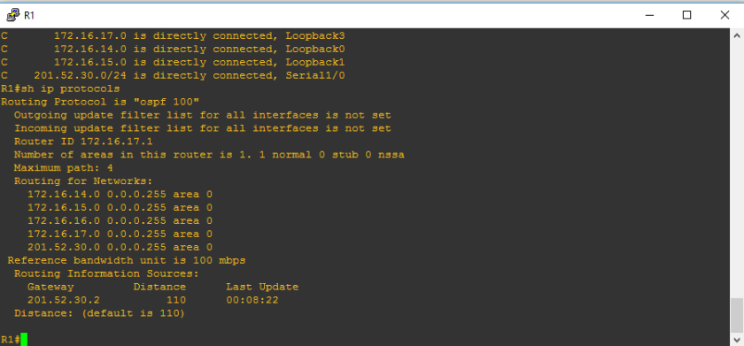
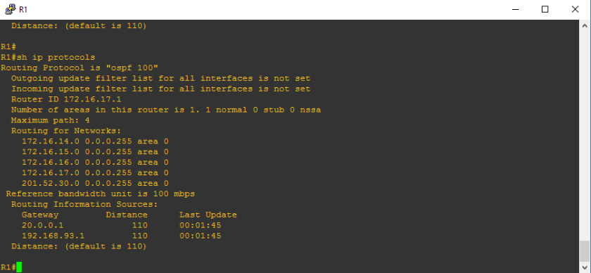
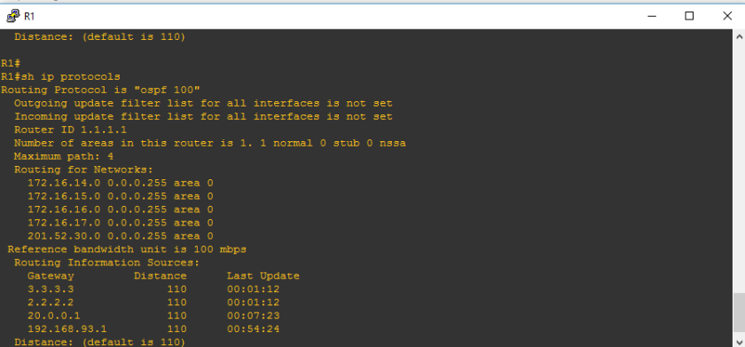
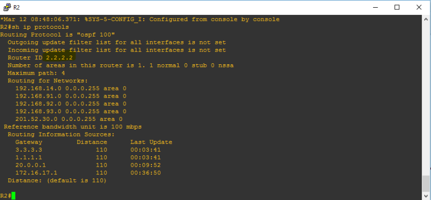
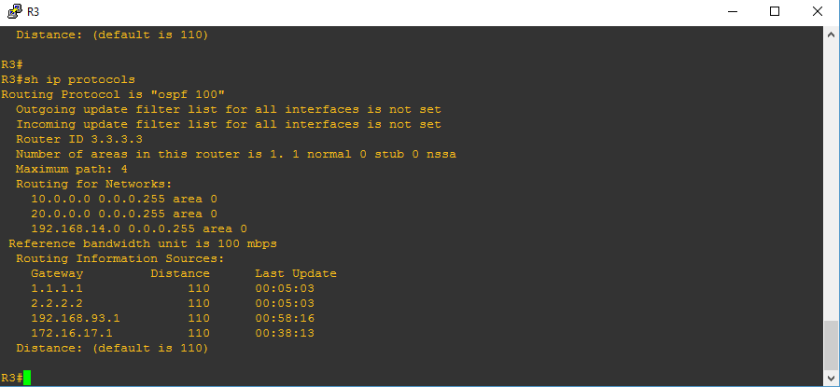
Let’s check and analyze the routing table of each routers:

We are getting successful route from upper left router to either middle right, top or bottom routers because we configured it manually. We can verify that on the picture above. Let’s say that network address 200.0.0.8, though it is not directly connected to BPO MAIN BLDG 1 but it was learned manually by the help of 200.0.0.2. Also, let us check the highlighted [1/0] which represents the administrative distance and the metric which serves as the reference of what is the best path.
Other routing table shows:


Alright, I’m challenging everyone to interpret how each routers learned the route to the network destination. It will be just easy to explain here but will take time because there are 6 routers. But seriously, it is just easy interpreting the routing table.
************************END OF BLOG**********************************