OSPF part 2: Router-ID

Hi mate, good morning!  We will be dealing back with our network topology that we configured before.o7a

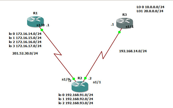
You wonder what is router-id right? Router-id is the identifier of router on the perception of another router. I am sorry if it is a little bit confusing. Here’s how it goes, R1 would identify R2 by R2’s router-id and R2 would identify R1 by R1’s router ID.

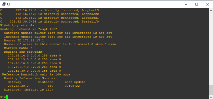
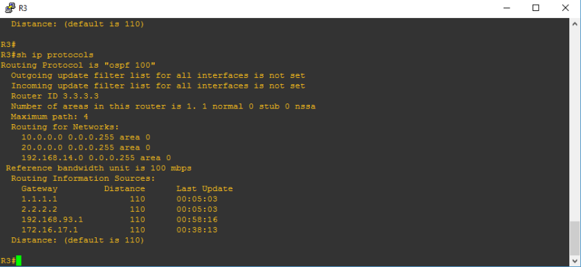
I hope that your GNS3 is now ready. Kindly input ” show ip protocols”

12a.PNG

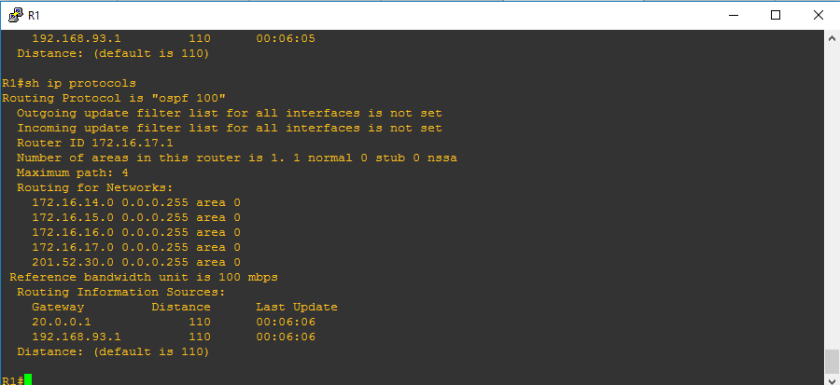
Router-ID is an important concept in each routing protocols specially with OSPF and EIGRP. When R1 would like to connect to R2, of course R1 should introduce himself and R1 will introduce his router-id as his name. On the figure above, you would see ROUTING INFORMATION SOURCES and the ip address written on the gateway column is the router-id. So how would we know the router-id which should be listed? There are hierarchy to know the router-id and these are the following from the top priority to the least priority.

1.) Hard-coded router-id – this is the router-id that we manually configure.

2.) Highest loopback address- very self-explanatory, the loopback address which has highest numerical value

3.)Highest ip address-   very self-explanatory, the ip address which has highest numerical value

If ever you wonder why there are two router-ids on the “show ip protocols” command, it was because there are two neighbor routers.

12b

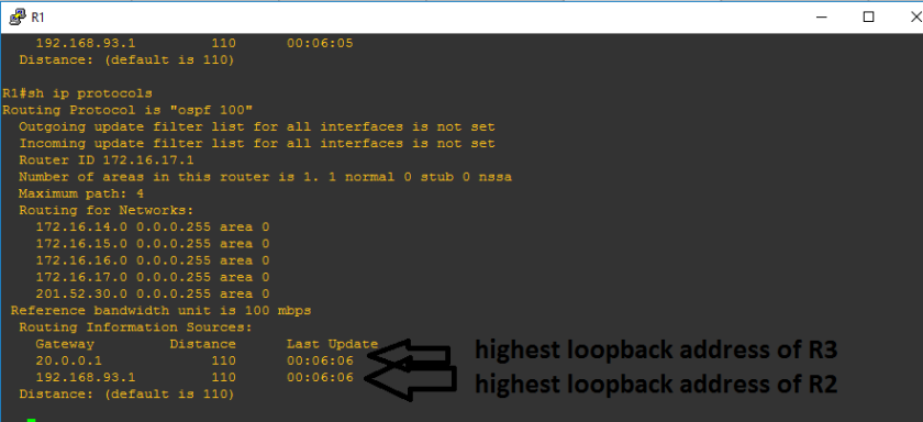
Before we proceed with manually configuring the IP address, let us try to remove the loopback addresses, to know if removing the loopback address would lead us that the highest IP address will be the last resort if there are no loopback address and no hard-coded router-id. Since it is very obvious on the figure above that highest loopback address was used instead of hard coded router-id and highest IP address.

Let us try to implement:

on R2

conf t

int lo 0
ip address 192.168.91.1 255.255.255.0
shut
int lo 1
ip address 192.168.92.1 255.255.255.0
shut
int lo 2
ip address 192.168.93.1 255.255.255.0
shut
exit
do sh ip int br


on R3

en
conf t

int lo 0
ip address 10.0.0.1 255.255.255.0
shut
int lo 1
ip address 20.0.0.1 255.255.255.0
shut
exit
do sh ip int br


As you observed, the router-ids are not changed. Why is it happening? because R1 already knows R2 as 192.168.93.1 and R1 already knows R3 as 20.0.0.1 and so in the event there are changes with R2 and R3, R1 would still identify R2 and R3 as their original router-ids unless R2 and R3 reintroduce themselves to R1.  In order that R2 and R3 will reintroduce themselves to R1, we need to restart the routers.

12c


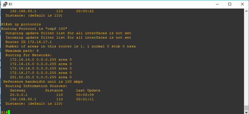
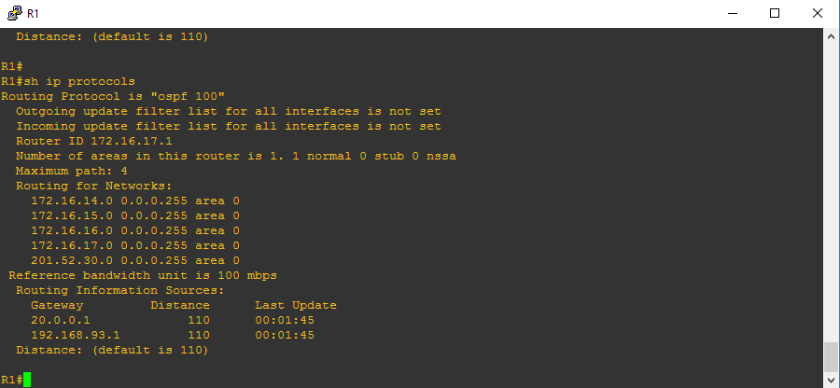
Alright, the routers just got restarted, and let us check sh ip protocols command,

12d

You would see that 201.52.30.2 which is not a loopback nor hard-coded router-id on the routing information sources. Due to incorrect configuration, only one router-is is known by R1 and  R3’s router-id is not known by R1. Also, you will see above the the router-id of R1 still remain as 172.16.17.1 since we did not touch that.So let us retrieve the loopback addresses.

12e.PNG

***********************************************************************Configuration of Router-IDs

Mate, it is very clear that the reason why we consider hard-coded router-ids as top of the hierarchy is because it is something stable or meaning to say it will not vary. What I mean is that in the event that the interface with highest ip address went down or the loopback address was accidentally went to administratively down, it may cause misconfiguration which will lead to network disruption.So it is advisable in the industry, to configure router-id. So let us take note that router-id doesnt necessarily mean that it is an ip address though it looks like ip address.

Let us designate the router-ids of routers:

R1 1.1.1.1

R2 2.2.2.2

R3 3.3.3.3

SYNTAX:

en
conf t
router ospf  {process#}
router-id x.x.x.x
do clear ip ospf process  —> it will appear and it is your discretion whether to restart router or clear the router-ids, then type  YES
do wr
exit
do sh ip protocols

@R1

en
conf t
router ospf 100
router-id 1.1.1.1
do clear ip ospf process  ; type YES
do wr
exit
do sh ip protocols


@r2

en
conf t
router ospf 100
router-id 2.2.2.2
do clear ip ospf process; type YES
do wr
exit


@R3

en
conf t
router ospf 100
router-id 3.3.3.3
do clear ip ospf process; type YES
do wr
exit


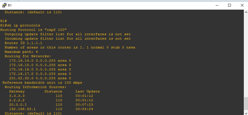
And there you go, we will check the router-id of R1, please take note that old router-ids may take time to be removed on the sh ip protocols table
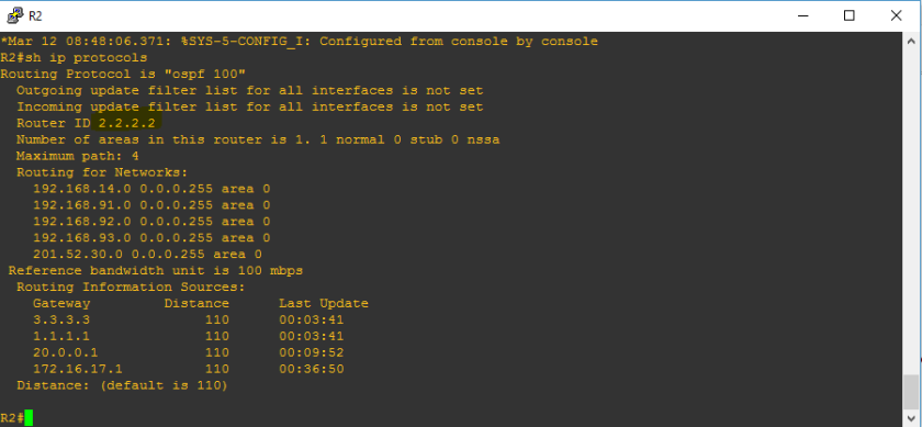
12f

Let’s check R2

12g


Let’s check R3

12h

And there dyou go! We are able to at least configure router id on OSPF protocol. Next ospf process that we will configure is passive inteface and security features of OSPF. After that, we will explain how OSPF works. Stay tuned!


2.8 Configure and verify Layer 2 protocols: CDP and LLDP

Alright, so let me just introduce CDP or cisco discovery protocol. It is very obvious that CDP is a cisco proprietary protocol and the goal of this protocol is to provide a specific cisco device an insight of the topology. I have here a show command for cdp:

show cdp neighbors

R1#en
R1#show cdp neighbors
Capability Codes: R – Router, T – Trans Bridge, B – Source Route Bridge
S – Switch, H – Host, I – IGMP, r – Repeater, P – Phone
Device ID Local Intrfce Holdtme Capability Platform Port ID
R3 Ser 3/0 160 R PT1000 Ser 3/0
R2 Ser 2/0 122 R PT1000 Ser 2/0
Switch Fas 0/0 172 S 2960 Fas 0/1

First, let me define the terms you see above:

  1. Device ID- name of the cisco device connected on the device reference( device reference for this show command is R1) so device id refers to cisco devices connected to R1
  2. Local interface- interface of device reference ( R1 as of the moment) which is connected to neighbor devices

Let’s say , from show commands above, R1 has interface Serial 3/0 which is connected to R3, ok mate?

3. Capability–> there is a label above that says the capability of the device whether it is router or switch

4.Platform —> the model of either the switch or router or any cisco devices connected. From the figure above we can conclude that Switch model used is catalyst 2960

5. Port ID –> the interface of the neighboring device wherein the device reference is connected.

Let us conclude the show commands above:

1st. R1 which has serial interface 3/0 is connected to R3 also with serial interface 3/0 and both of them has routing capabilities and is cisco model PT1000

2nd R1 which has serial interface 2/0 is connected to R3 also with serial interface 2/0 and both of them has routing capabilities and is cisco model PT1000

3rd R1 which has fastethernet interface 0/0 is connected to switch which has fastethernet interface 0/1 and switch has switching capabilities ? hahaha and the model is cisco catalyst 2960.

And the network topology is:

eeeeeeeee

So, we conclude that using CDP, we can have a clear picture of the topology. If you want more details specially the ip address connected, you can use show  cdp  neghbors details

show cdp neighbors detail

R1#show cdp neighbors detail

Device ID: R3
Entry address(es):
IP address : 172.16.14.2
Platform: cisco PT1000, Capabilities: Router
Interface: Serial3/0, Port ID (outgoing port): Serial3/0
Holdtime: 163

Version :
Cisco Internetwork Operating System Software
IOS ™ PT1000 Software (PT1000-I-M), Version 12.2(28), RELEASE SOFTWARE (fc5)
Technical Support: http://www.cisco.com/techsupport
Copyright (c) 1986-2005 by cisco Systems, Inc.
Compiled Wed 27-Apr-04 19:01 by miwang

advertisement version: 2
Duplex: full
—————————

Device ID: R2
Entry address(es):
IP address : 192.168.31.2
Platform: cisco PT1000, Capabilities: Router
Interface: Serial2/0, Port ID (outgoing port): Serial2/0
Holdtime: 124

Version :
Cisco Internetwork Operating System Software
IOS ™ PT1000 Software (PT1000-I-M), Version 12.2(28), RELEASE SOFTWARE (fc5)
Technical Support: http://www.cisco.com/techsupport
Copyright (c) 1986-2005 by cisco Systems, Inc.
Compiled Wed 27-Apr-04 19:01 by miwang

advertisement version: 2
Duplex: full
—————————

Device ID: Switch
Entry address(es):
Platform: cisco 2960, Capabilities: Switch
Interface: FastEthernet0/0, Port ID (outgoing port): FastEthernet0/1
Holdtime: 175

Version :
Cisco IOS Software, C2960 Software (C2960-LANBASE-M), Version 12.2(25)FX, RELEASE SOFTWARE (fc1)
Copyright (c) 1986-2005 by Cisco Systems, Inc.
Compiled Wed 12-Oct-05 22:05 by pt_team

advertisement version: 2
Duplex: full


show cdp neighbors detail just give you more details like the ip addresses involved and the IOS involved but it is basically almost the same. It can be helpful specially if the network topology design has lost.

Let me take first my breakfast mate!

****************************After Breakfast***************************

LLDP ( Link-Layer Discovery Protocol)

Yeah! I’m back after that heavy breakfast that I had. Seriously, I am planning to discuss LLDP and the next blog post. Upon researching, I realized that CDP is an IEEE standardized neighbor discovery protocol as a counterpart of CDP. It is registered as IEEE 802.1AB and it almost function as the same but LLDP is created to support non-cisco devices including VOIP phones and switchs.

Use show lldp to verify

Most of the cases, CDP is used to discover neighbor devices but it is a good to know thing  for further troubleshooting purposes what is LLDP just like I’ve learned it 30 minutes ago.

******************************End of Blog*******************************