ospf part7: OSPF areas, router types, ospf routes & LSA types

Hi mate, I’m back once again. This time will dig deeper on OSPF.  We will discuss some of important concepts on OSPF which will be useful as we transition on CCNP-Route


OSPF Areas

  • Why do we implement areas on ospf network and what will be the use of that?
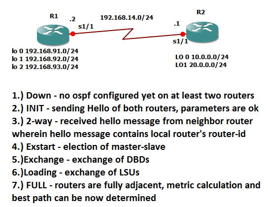
  • –> Here’s how it goes, when there is a network changes  let us say a new network  address was added on ospf topology with 50 routers, let us go back on ospf process, the local router will create its own LSA, will send hello to multicast address 224.0.0.5 or all ospf speaking routers and will expect for a hello message which has its own router-id and so on and so forth that it reaches the stage of asking for LSU. That seems to be not a complicated process however our goal in routing is that all routers can reach or ping each others even though there are 50 routers in the network. This scenario is feasible but this will lead to excessive CPU utilization and slower convergence. Why? because if there are 50 routers connected on that ospf network, it may require time for router LSAs to be propagated from routers near the originating router to router remote to the originating router.


Solution for that is implementing OSPF areas. How does it work and how does it help?

First let us define OSPF areas as a logical grouping of OSPF areas. Let us remember that the LSA that routers send on our discussion awhile ago is just router LSA. Router LSA is only sent on to ospf speaking routers within the same area. When we activate an ospf network, say for example when we type:
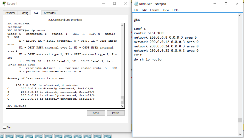
en
conf t
router ospf 100
network 10.0.10.0 0.0.0.255 area 0

There are three effects that will happen to the network:

1.) Activates all the interfaces that can be covered on the network statement- if we got interfaces  with ip addresses 10.0.0.1 , 10.0.0.2 and 10.0.0.9, all of those interfaces will be activated since they are covered in the network statement

2.) Advertises the network address of the activated interface

3.) Puts the activated interface on the area specified.

Since our goal is to avoid slow convergence and  high CPU utilization, router LSA is sent only on the area where the local router belongs. So the question that I guess that runs on your mind is how will the information or LSA be sent to routers on different areas if the router LSA is sent only to  the area where the local router belongs. The solution is that another LSA is created and advertised but we will go further to that but let me discuss first an important concept before we proceed to that.

OSPF Area types

1.) Regular area- any areas that is not area 0

2.) Backbone Area – area 0

Just take the definition as it is so that you will understand some other OSPF terminologies which we will discuss later.

OSPF router types

1.) Internal routers- routers that belong only to single area

2.) Area Border Routers (ABR) – routers that connect regular area to backbone area. The name itself defines that it is the border between regular and backbone area.

3) Backbone Router – routers with at least one interface which is connected to backbone area or area 0

4.) External routers – these are routers that are connected to internet, non-ospf router and other ospf AS system. Other OSPF AS system means that it runs OSPF as well but on the other company. Let us say it runs OSPF on AT&Tand the external router runs OSPF on Sprint.


19A1.png


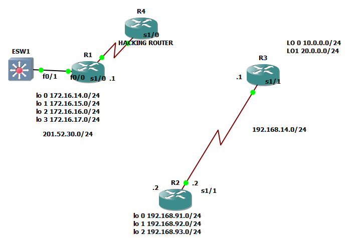
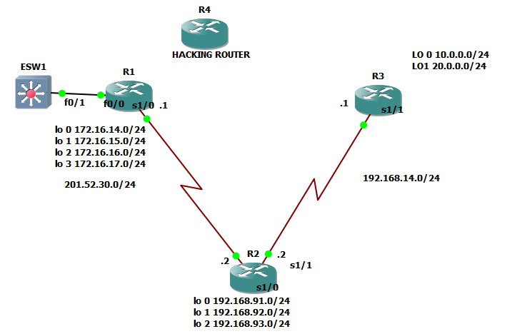
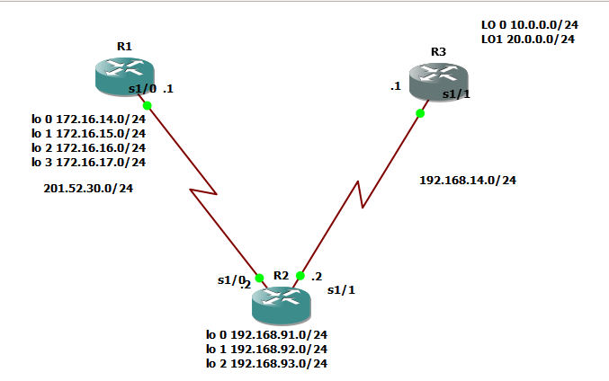
Alright, let us try to identify the terminologies that we discussed before and let us identify those on the image above.

OSPF area types:

a.)Regular Area- area 15 and area 25; defined as area 0

b.) Backbone Area – of course no other than but area 0


OSPF router types:

a.)Internal routers-  defined as router with single area; those are R1, R3,R5,R6, R8 and R9 on the picture above

2.) Area Border router – defined as router that connects backbone area and regular area, those are  R2 and R7 on the picture above

3.) Backbone Router – define as router with at least one interface connected to area 0

So on the picture above, those are routers R2,R4, R5, R6, and R7

4.) External routers – let us say that R6 is connected to a router that only runs EIGRP, it will be removed on the list of internal routers but considered as external routers.

Be reminded that a router can be ABR and backbone router at the same time. Or a certain router on an OSPF network can have two classification of ospf router types.

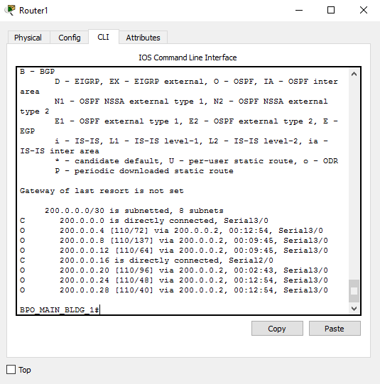
Three types of OSPF routes:

1.) Inter- Area Routes-  routes within the different area; denoted by ‘O IA” on the routing table

2.) Intra-Area routes- route within the same area; denoted by ‘O” on the routing table

3.) External Routes – routes from outside ospf domain;denoted by ‘O E1 or OE2″ on the routing table


Alright! So I am now able to define those OSPF terminologies and hopefully you understood it by example. So we will be dealing back with the question awhile ago: if router LSA is only sent to routers on the same area then how will the LSA created by the originating router be advertised to routers on different area? The solution is

SUMMARY LSA

The scenario goes like this

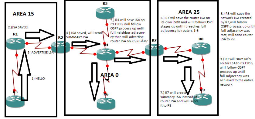
1.) A network was added on R3 so it will update its LSA and will send hello to R1.

2.) R1 will save  R3’s LSA and will send hello back to R1 up until R1 and R3 is fully adjacent.

3.) R1 will advertise R3’s router LSA to R2

4.) R2 will save R3’ s router LSA advertised by R1 and will follow OSPF process up until R2, R1 and R3 are fully adjacent. Now, since R2 is the ABR, its task is to create summary LSA to advertise the router from area 15 to area 0. Be reminded that summary LSA is only create by ABR.

So if we will define SUMMARY LSA – it is the LSA created by ABR to advertise router LSA of a router on different area to another area.19A2


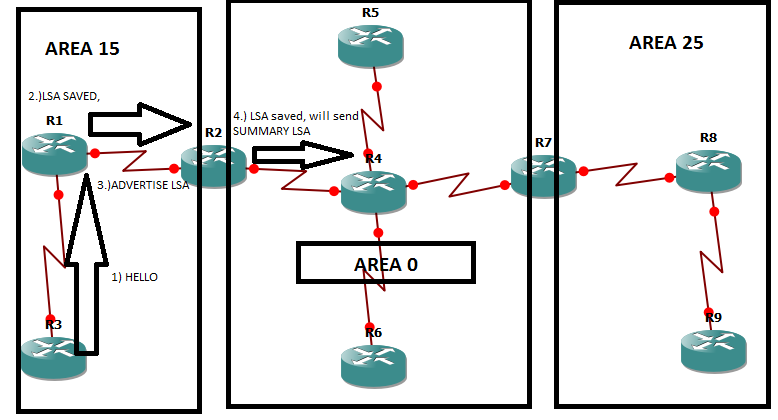
The thing here is that on R4’s perspective, he only got one LSA from R1, R3 and R2 . Meaning to say the router LSAs which must be advertised by R1, R2 and R3  are viewed by R2 as just one LSA or summarized as SUMMARY LSA. So on R4’s perspective after full adjacency on all routers, R4 only got 4 neighbors instead of 9 routers.

We will continue the scenario and definitely I don’t have to elaborate other steps since it will be repetitive. The steps and scenario will be on the picture.

19A3.png

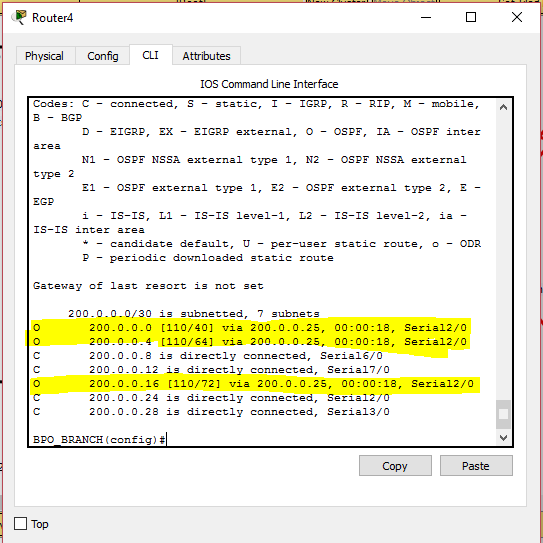
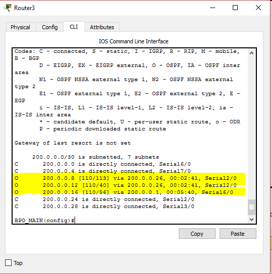
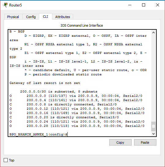
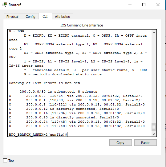
Alright! We already achieved Full adjacency on all routers, hopefully you understood the ospf terminologies, ospf areas, router types, ospf routes and the new LSA that we got.

Talk to you soon mate!


ospf part 6: how ospf works? ospf process & Hello content

Hey there! To learn a protocol, always asks how it works. Always remember, protocol is  a set of procedures or set of rules. In ospf, there are actually 7 process or steps to achieve neighbor adjacency. Let us first enumerate those processes.

1.) Down

2.) INIT

3) 2-way

4.) Exstart

5.) Exhange

6.) Loading

7.) Full

1.) DOWN- There will be only two reasons why an ospf network would go down

a.)When an interface is configured with an stafic ospf neighbor

  • this will be topic which is covered on CCNP – route wherein instead that a hello message is sent to a multicast address, it will be sent to just unicast address


b.) When hello timer expires and then dead timer takes place.

For us to easily understand, those timers and multicast address that I am telling you. We will discuss first hello message content and its timer.

Hello Message Contents:

1.) Router-ID of local router- router-id of the router which will send hello message

2.) Area-ID- area id of the interface of the local router

3.) Address & Subnet Mask – address & subnet mask of the interface

4.) Authentication type- the password or passive interface configured on the router interface

5.) Hello & Dead Interval – there dyou go!- Hello and dead interval are check alive timers. Hello interval is a message sent by local router to check if neighbor routers are still alive. If neighbor routers did not response after  the default value of 10 seconds, it will wait for 40 seconds for it to declare that the neighbor is officially down. Please take note that 40 seconds is just the default value of ospf dead timer. The values can be also configured.

6.) Router interface priority – likewise I mentioned on the previous blog, priority is used on election of master-slave router. We will further discuss this as we  go on, but just to give you a hint, priority value is used who will be the first router to send its LSDB

7.) DR  & BDR information – let us make it simple, these can be compared to the master-slave routers. DR stands for designated router and BDR stands for back-up designated router. We will dig deeper on this on the next blog pages

8.) Router-ID of the local router’s neighbor – this appears on the neighbor table of the local router

Alright so those are the contents of the hello message which will be sent by the local router to the neighbor router and also the local router should expect those information to be sent by neighbor router to him.

Always remember mate, that there can be multiple protocols which also sends information like hello message or its counterpart. So, the question is how will a router knows that the hello message  is supposed to be sent to him.

17A1

On the image above, the question is how will neighbor router will know that it is that he is the recipient of the hello message? Also how will R3 would know that since EIGRP is configured to him, he is not recipient of the hello message? The message is sent with destination address of 224.0.0.5 which is a multicast address. I mean to say that the hello message is broadcast to the network but intended only to the group of routers that run OSPF protocol.

Let us say that R3 drops the packet since he is not the recipient of the hello message and R1, the neighbor router received the hello message of R2. What will happen next?

R1 will counter check the hello sent by R2. And the following should match:

1.) Area ID – if R1 is on area 0, R2 must be also on area 0

2.) Area type – we will discuss this further but just to give you a hint these are normal, stubby, not so stubby area., sounds very complex but we will discuss this as we go on

3.)Network address & Submet mask

4.) Hello & Dead intervals

5.) Authentication information

6.)Router-ID must be unique

***********************************************************************

OSPF STAGE 2: INIT

How we will transition from DOWN state to INIT ?


Here’s how it goes! Let play a scenario wherein R1 and R2 is trying to establish neighbor adjacency

Step1 ospf interface of R1 got activated,  R1 will create its own LSA, remember LSA? HEHE,  R1 will send hello message to its neighbor but since no neighbor routers got ospf activated, hello timer will expire and will proceed to dead timer.

Step2  ospf interface of R2 once got activated,R2 will create its own LSA, R2 will send hello to R1. (

Step3 R1 will counter check the hello message sent of R2

Step 4 once all the parameters are achieved, R1 will add R2 as its neighbor and then the OSPF  process will transition from DOWN to INIT, so let us define INIT stage

INIT STAGE – is when all hello parameters are and then the neighbor router is added on neighbor table of R1, it will remain on INIT stage until it received a hello with its own router-ID. Sound confusing? we will explain that further as we transition to 2-way

Step 5 – Since R1 already added R2 as its own neighbor, R1 will send hello message once again to R2 with hello message wherein the neighbor is R2. Since the hello message has R2’s router-id which will be sent to R2, therefore it is now the time to transition to 2-WAY

***********************************************************************

2-WAY –>  If a router received a hello from a neighbor and sees its own router-id

is included in the list of neighbor

Step 6

18a.png

Let us have a recap from step 5, since R1 is on INIT state and sent hello to R2 with its neighbor router-id as hello content, R2 will add R1 as its neighbor router and will skip to 2-way, Step 6  would be R2 will send hello to R1 with its R1’s router-id as hello content then  R1 will transition to 2-WAY. Once both routers are on 2-way state, it will transition to EXSTART

***********************************************************************

EXSTART – the process of election on routers who will send its DBD

DBD – database descriptor – summary of router-ids of all LSAs inside LSDB

Step 7 Election will be on master-slave process

Master- highest router -id

Slave – lowest router-id

***********************************************************************

EXCHANGE – when we already figured out the master and the slave among routers.

Step 8 On our case, R2 will be the one who will send DBDs. R1 will just confirm that R1 & R2 share the same DBD as a reply ro R2

***********************************************************************

LOADING – it is the process of checking the LSDB of those routers involved to verify that they share the same LSDB

Step 9 After exchange of DBDs , if there are some neighbor information that they missed, master router will send a link state request which will lead to link state update and link state acknowledgment. Here’s how it goes!

Let’s say:

R2 ( master) : hi R1 here  is my ospf database

R1 ( slave) : Got it master!  I will try to counter-check and double check it!

Let’s say R2 has a new network configured to its interface and that network will be 10.0.21.0/24

R1 ( slave): R2 ( master ) , it seems like I don’t have yet the new network 10.0.21.0/24 configured to your interface, can I request to have that one . – THIS IS WHAT WE CALL LINK STATE REQUEST

R2( master) : Ohh oaah! I missed to inform you that, ok  no worries, I will provide you that network as LINK STATE UPDATE

R1( slave): Thank you so much master, I hope that you consider this one as LINK STATE ACKNOWLEGMENT to inform you that I already received the new neighbor information that you got.

***********************************************************************

FULL- we are now done with the final OSPF process wherein we have full neighbor adjacency. Loading state will be finished if all the routers have the same LSDB

***********************************************************************

Just a quick summary of OSPF process!

18b

Oh yeah! Apologies if it is very lengthy  and boring but I hope that I was able to educate you today!


ospf part 4: ospf authentication

Hi there mate! This will be the last discussion on OSPF configuration. The rest of the OSPF topics will discuss how OSPF works and the content of Hello packet. The last topic that we had was configuring passive interfaces for security reasons. This time, we will configure OSPF with authentication using encrypted passwords. The need for configuring authentication is very simple, it is to provide security to active interfaces.  I mean active interface are those interfaces that receives and sends hello or OSPF updates. They cannot be a passive interface so authentication will be the best process to secure those interfaces.

Just come to imagine the scenario below wherein12a1

Instead that the interface serial 1/0 of router 1 is connected to router2. It was connected to hacking router so it will lead to security breach.

So let us get back to our original topology.

12a2.PNG

Authentication SYNTAX:

en 
conf t
router ospf {process#} <— process # 
area {area#} authentication message digest < — we set authentication on the entire area on specific router
exit
int serial x/x
ip ospf message-digest-key 1 md5 {password} <— the authentication used is MD5 , you can further check on google how it works 

Note: 1.) We set password on each interface since the security breach may happen on each                     interface

2.) We can set multiple passwords on each interface: the syntax will follow:


int serial x/x
ip ospf message-digest-key 1 md5 {password}
ip ospf message-digest-key 2 md5 {password}

Very easy configuration right? So let us try to check the configuration on each router.
en
conf t
router ospf 100
area 0 authentication message-digest
exit
int se 1/0
ip ospf message-digest-key 1 md5 cisco

12a3

As we can see, opsf neighbor adjacency went down. It is for the reason that the neighbor router is not also configured with authentication and so they will not established neighbor relationship. Another way to verify: show ip ospf neighbor

12a4

So no neighbor relationship established. We can now continue with R2 authentication configuration:

@r2

en
conf t
router ospf 100
area 0 authentication message-digest
exit

12a5

As I go on, I can see that neighbor adjacency went down even without configuring the interfaces. It is for the reason that authentication was configured globally so it affects all the interfaces involved. We need to go by interfaces so that it would be more secured and to specify the password. How we will enter a locked door without a key? There should be a key. We need to specify the password / key-string. Below shows that no neighbor adjacency was established.

12a6

Let us continue the configuration:

int se 1/0
ip ospf message-digest-key 1 md5 cisco
int se 1/1
ip ospf message-digest-key 1 md5 cisco
exit

Below is what happened when I configured authentication on R2. We can see that serial 1/0 went up since it is connected to R1 and R1 has already md5 configuration. We can see on neighbor table that only R1 exists since R3 doesnt have md5 configuration.

12a7.png

Below is the neighbor table of R1, it shows that he can now see R2

12a8

Lastly, let us configure R3:
en
conf t
router ospf 100
area 0 authentication message-digest
exit
int se 1/1
ip ospf message-digest-key 1 md5 cisco
exit

12a9.png

Nothing much special with R3 configuration. We already discussed that serial 1/1 is possible to turn up since all routers has already md5 authentication and also router 2 appears on neighbor table. One thing that I can add to is that you alway see that term “from loading to FULL”. Those are stages of neighbor adjacency which we will discuss on the next topics.

I guess right now, you wonder how ospf works? We will discuss that on the next topic.

OSPF part 2: Router-ID

Hi mate, good morning!  We will be dealing back with our network topology that we configured before.o7a

You wonder what is router-id right? Router-id is the identifier of router on the perception of another router. I am sorry if it is a little bit confusing. Here’s how it goes, R1 would identify R2 by R2’s router-id and R2 would identify R1 by R1’s router ID.

I hope that your GNS3 is now ready. Kindly input ” show ip protocols”

12a.PNG

Router-ID is an important concept in each routing protocols specially with OSPF and EIGRP. When R1 would like to connect to R2, of course R1 should introduce himself and R1 will introduce his router-id as his name. On the figure above, you would see ROUTING INFORMATION SOURCES and the ip address written on the gateway column is the router-id. So how would we know the router-id which should be listed? There are hierarchy to know the router-id and these are the following from the top priority to the least priority.

1.) Hard-coded router-id – this is the router-id that we manually configure.

2.) Highest loopback address- very self-explanatory, the loopback address which has highest numerical value

3.)Highest ip address-   very self-explanatory, the ip address which has highest numerical value

If ever you wonder why there are two router-ids on the “show ip protocols” command, it was because there are two neighbor routers.

12b

Before we proceed with manually configuring the IP address, let us try to remove the loopback addresses, to know if removing the loopback address would lead us that the highest IP address will be the last resort if there are no loopback address and no hard-coded router-id. Since it is very obvious on the figure above that highest loopback address was used instead of hard coded router-id and highest IP address.

Let us try to implement:

on R2

conf t

int lo 0
ip address 192.168.91.1 255.255.255.0
shut
int lo 1
ip address 192.168.92.1 255.255.255.0
shut
int lo 2
ip address 192.168.93.1 255.255.255.0
shut
exit
do sh ip int br


on R3

en
conf t

int lo 0
ip address 10.0.0.1 255.255.255.0
shut
int lo 1
ip address 20.0.0.1 255.255.255.0
shut
exit
do sh ip int br


As you observed, the router-ids are not changed. Why is it happening? because R1 already knows R2 as 192.168.93.1 and R1 already knows R3 as 20.0.0.1 and so in the event there are changes with R2 and R3, R1 would still identify R2 and R3 as their original router-ids unless R2 and R3 reintroduce themselves to R1.  In order that R2 and R3 will reintroduce themselves to R1, we need to restart the routers.

12c


Alright, the routers just got restarted, and let us check sh ip protocols command,

12d

You would see that 201.52.30.2 which is not a loopback nor hard-coded router-id on the routing information sources. Due to incorrect configuration, only one router-is is known by R1 and  R3’s router-id is not known by R1. Also, you will see above the the router-id of R1 still remain as 172.16.17.1 since we did not touch that.So let us retrieve the loopback addresses.

12e.PNG

***********************************************************************Configuration of Router-IDs

Mate, it is very clear that the reason why we consider hard-coded router-ids as top of the hierarchy is because it is something stable or meaning to say it will not vary. What I mean is that in the event that the interface with highest ip address went down or the loopback address was accidentally went to administratively down, it may cause misconfiguration which will lead to network disruption.So it is advisable in the industry, to configure router-id. So let us take note that router-id doesnt necessarily mean that it is an ip address though it looks like ip address.

Let us designate the router-ids of routers:

R1 1.1.1.1

R2 2.2.2.2

R3 3.3.3.3

SYNTAX:

en
conf t
router ospf  {process#}
router-id x.x.x.x
do clear ip ospf process  —> it will appear and it is your discretion whether to restart router or clear the router-ids, then type  YES
do wr
exit
do sh ip protocols

@R1

en
conf t
router ospf 100
router-id 1.1.1.1
do clear ip ospf process  ; type YES
do wr
exit
do sh ip protocols


@r2

en
conf t
router ospf 100
router-id 2.2.2.2
do clear ip ospf process; type YES
do wr
exit


@R3

en
conf t
router ospf 100
router-id 3.3.3.3
do clear ip ospf process; type YES
do wr
exit


And there you go, we will check the router-id of R1, please take note that old router-ids may take time to be removed on the sh ip protocols table

12f

Let’s check R2

12g


Let’s check R3

12h

And there dyou go! We are able to at least configure router id on OSPF protocol. Next ospf process that we will configure is passive inteface and security features of OSPF. After that, we will explain how OSPF works. Stay tuned!


3.9 OSPF (Open Shortest Path First Version 2) Part 1: Configuration and Router-ID

Happy New year Mate! We are moving on my most favorite routing protocol—- OSPF. I can still remember during the technical interview, I was asked what is my most favorite routing protocol and why? Since the only routing protocol which was fresh in my mind during that time is OSPF, I answered OSPF because blah blah blah. A follow-up question came along—> how OSPF works? To make the long story short, OSPF saved my ass. And that is my story about my most favorite routing protocol.

Too much for introduction, below will be the trivial information that you need to know about OSPF.

1.) link-state protocol( we will discuss this later)

2.) Administrative distance of 110- just a recap administrative distance is the reference of the router which protocol router should follow in the event that there are multiple protocols running on it.

3.) Metric–> cost, in the event that there are multiple paths going to a specific host, cost  of the ospf operated router will serve as the reference of the router. The lower the cost, the more the router will follow that path.

4.)Dynamic routing protocol- all of the other routing protocols that we will be discussing are dynamic routing protocol. Dynamic routing protocols are protocols that will adapt for  any network changes. Lets’s say link 1 fails, you don’t have to manually reconfigure the device just to troubleshoot the network failure.

***********************************************************************

SYNTAX AND CONFIGURATION:

You wonder why we proceed already with the configuration without knowing the concept or how ospf works? –> because it will be better if we will see the terminologies involved and how it will affect the network.Also, we will just do the basic configuration, addendum will follow to explain their functions.

–> I preferred to it this way for easy explanation and to avoid redundancy.

SYNTAX:

en
conf t
router ospf {Process #}
network { directly connected network address} {wildcard mask}(mandatory) {area#}
exit

Lemme explain the syntax first

1.) Process # – it wont hurt much the network whether devices have different routing process, it’s just part of the syntax.

2.) Directly connected network address – when you do ” show ip route” on a specific router, we will include all network address listed.

3.) Wildcard mask- It is exact opposite of subnet mask. It gives the same concept to be more specific of the network. The reason why there are two concepts like subnet mask and wildcard mask though they function almost the same is because using wildcard mask will gives faster decoding because of logical functions used e.g. NAND, AND.

4.) Area #–> we will deal further with area # but one thing to remember is that interfaces that face each other should have the same area#

Network topology below( same topology as static configuration):

0101a.PNG

initial configuration:

@ BPO_MAIN_BLDG_1

enable
conf t
line console 0
password cisco
logging sync
exec-timeout 20 30
login
exit
line vty 0 15
password cisco
logging sync
exec-timeout 20 30
login
exit
hostname BPO_MAIN_BLDG_1
enable secret class
service password-encryption
no ip domain-lookup
banner motd “AUTHORIZED ACCESS ONLY”
do wr

@BPO_MAIN_BLDG_2

enable
conf t
line console 0
password cisco
logging sync
exec-timeout 20 30
login
exit
line vty 0 15
password cisco
logging sync
exec-timeout 20 30
login
exit
hostname BPO_MAIN_BLDG_2
enable secret class
service password-encryption
no ip domain-lookup
banner motd “AUTHORIZED ACCESS ONLY”
do wr
@BPO_MAIN

enable
conf t
line console 0
password cisco
logging sync
exec-timeout 20 30
login
exit
line vty 0 15
password cisco
logging sync
exec-timeout 20 30
login
exit
hostname BPO_MAIN
enable secret class
service password-encryption
no ip domain-lookup
banner motd “AUTHORIZED ACCESS ONLY”
do wr

@BPO_BRANCH
enable
conf t
line console 0
password cisco
logging sync
exec-timeout 20 30
login
exit
line vty 0 15
password cisco
logging sync
exec-timeout 20 30
login
exit
hostname BPO_BRANCH
enable secret class
service password-encryption
no ip domain-lookup
banner motd “AUTHORIZED ACCESS ONLY”
do wr
@BPO_BRANCH_ANNEX_1
enable
conf t
line console 0
password cisco
logging sync
exec-timeout 20 30
login
exit
line vty 0 15
password cisco
logging sync
exec-timeout 20 30
login
exit
hostname BPO_BRANCH_ANNEX_1
enable secret class
service password-encryption
no ip domain-lookup
banner motd “AUTHORIZED ACCESS ONLY”
do wr
@BPO_BRANCH_ANNEX-2
enable
conf t
line console 0
password cisco
logging sync
exec-timeout 20 30
login
exit
line vty 0 15
password cisco
logging sync
exec-timeout 20 30
login
exit
hostname BPO_BRANCH_ANNEX-2
enable secret class
service password-encryption
no ip domain-lookup
banner motd “AUTHORIZED ACCESS ONLY”
do wr
***************************
@ main bldg 1

en
conf t
int se 3/0
ip add 200.0.0.1 255.255.255.252
no shut
exit
int se 2/0
ip address 200.0.0.17 255.255.255.252
no shut
exit

@main bldg 2
en
conf t
int se 2/0
ip add 200.0.0.18 255.255.255.252
shut
no shut
exit
int se 3/0
ip add 200.0.0.5 255.255.255.252
shut
no shut
exit

@ BPO_MAIN

en
conf t
int se 6/0
ip add 200.0.0.2 255.255.255.252
no shut
exit
int se 7/0
ip add 200.0.0.6 255.255.255.252
no shut
exit
int se 2/0
ip add 200.0.0.25 255.255.255.252
no shut
exit
int se 3/0
ip add 200.0.0.29 255.255.255.252
no shut
exit
int fa 0/0
no shut
exit

@ BPO_BRANCH

en
conf t
int se 2/0
ip add 200.0.0.26 255.255.255.252
no shut
exit
int se 3/0
ip add 200.0.0.30 255.255.255.252
no shut
exit
int se 6/0
ip add 200.0.0.9 255.255.255.252
no shut
exit
int se 7/0
ip add 200.0.0.13 255.255.255.252
no shut
exit
int fa 0/0
no shut
exit
@bpo annex 1

en
conf t
int se 2/0
ip add 200.0.0.10 255.255.255.252
no shut
exit
int se 3/0
ip add 200.0.0.21 255.255.255.252
no shut
exit
int gigabitEthernet7/0
no shut
exit

@bpo annex 2

en
conf t
int se 2/0
ip add 200.0.0.14 255.255.255.252
no shut
exit
int se 3/0
ip add 200.0.0.22 255.255.255.252
no shut
exit
int gigabitEthernet 8/0
no shut
exit

Additional configuration:

we will configure the speed of the link

First let us check  the link of serial 6/0 of router 3, it is part of link 1 which must have 4096 kbps of speed.

0101b.PNG

R1 is already configured with the ff syntax:

conf t
int se 3/0
bandwidth 4096
exit
conf t
int se 2/0
bandwidth 3072
exit

0101c

R3 configuration:

conf t
int se 6/0
bandwidth 4096
exit
int se 7/0
bandwidth 2048
exit
int se 2/0
bandwidth 4096
exit
int se 3/0
bandwidth 6144
exit

0101d.PNG

There you go, we achieved the 4096 link speed requirement.

the continuation of  config:

@R1
conf t
int se 3/0
bandwidth 4096
exit
conf t
int se 2/0
bandwidth 3072
exit

@R2
conf t
int se 2/0
bandwidth 3072
exit
int se 3/0
bandwidth 2048
exit

@ R3
conf t
int se 6/0
bandwidth 4096
exit
int se 7/0
bandwidth 2048
exit
int se 2/0
bandwidth 4096
exit
int se 3/0
bandwidth 6144
exit

@ R4
conf t
int se 2/0
bandwidth 4096
exit
int se 3/0
bandwidth 6144
exit
int se 6/0
bandwidth 1024
exit
int se 7/0
bandwidth 4096
exit

@ R5
conf t
int se 2/0
bandwidth 1024
exit
int se 3/0
bandwidth 3072
exit

@R6
conf t
int se 2/0
bandwidth 4096
exit
int se 3/0
bandwidth 3072
exit


*************************OSPF CONFIG***********************************

set process# as 100

area as area 0


0101e.PNG

verify:

0101f.PNG
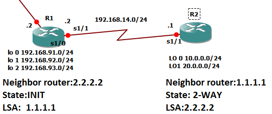
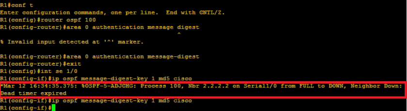
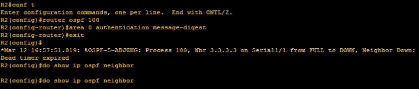
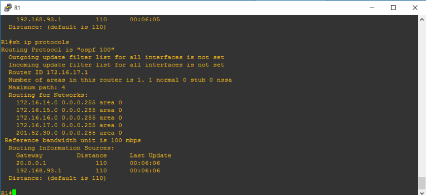
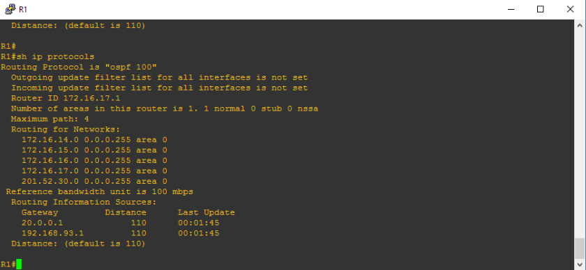
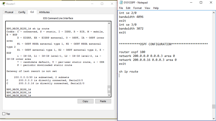
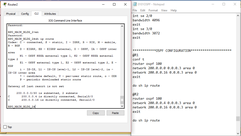
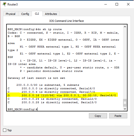
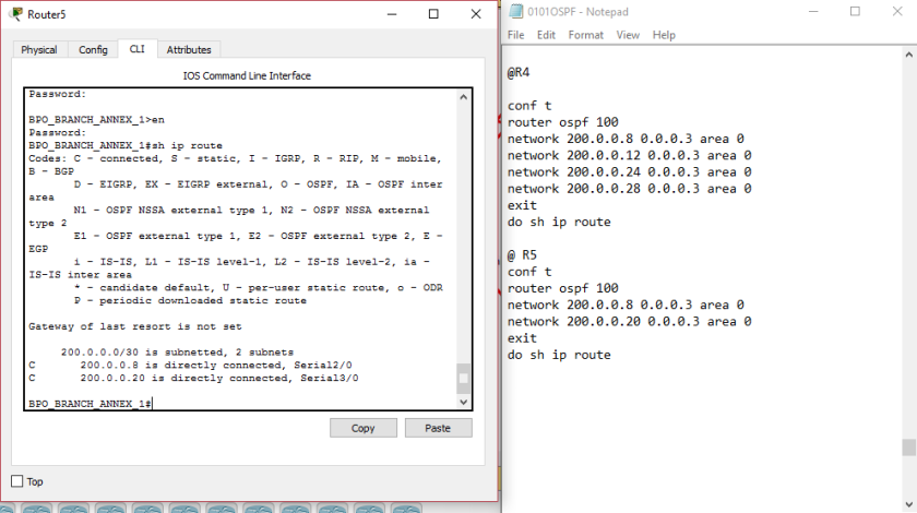
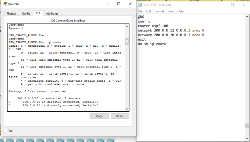
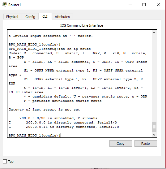
No OSPF yet on routing table because neighbor relationship is not yet established on other routers
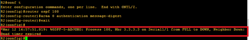
0101g.PNG

0101h

Aha! no ospf was establishe but, there is a highlighted notification sent

let’s try to verify once again after that notification appeared

0101i

There you go, OSPF was established, and we will analyze the highlighted network, we observed that the cost is 110 , which is the default cost, and the metric is 56. Also it was learned by the router by the help of 200.0.0.17

0101j.PNG

0101k.PNG

0101l.PNG

0101m.PNG

Actually, it takes me more than 6 seconds to see this routing table.

Also,let us check R3 once again:

0101n.PNG

0101o.PNG

0101p.PNG

Let’try the last router

0101p.PNG

0101q.PNG

Let us try to check once again the routing table of R1

0101r.PNG

************OSPF CONFIGURATION*********************
@R1
conf t
router ospf 100
network 200.0.0.0 0.0.0.3 area 0
network 200.0.0.16 0.0.0.3 area 0
exit

do sh ip route

@R2
conf t
router ospf 100
network 200.0.0.4 0.0.0.3 area 0
network 200.0.0.16 0.0.0.3 area 0
exit
do sh ip route

@R3

conf t
router ospf 100
network 200.0.0.0 0.0.0.3 area 0
network 200.0.0.4 0.0.0.3 area 0
network 200.0.0.24 0.0.0.3 area 0
network 200.0.0.28 0.0.0.3 area 0
exit
do sh ip route

@R4

conf t
router ospf 100
network 200.0.0.8 0.0.0.3 area 0
network 200.0.0.12 0.0.0.3 area 0
network 200.0.0.24 0.0.0.3 area 0
network 200.0.0.28 0.0.0.3 area 0
exit
do sh ip route

@ R5
conf t
router ospf 100
network 200.0.0.8 0.0.0.3 area 0
network 200.0.0.20 0.0.0.3 area 0
exit
do sh ip route

@R6
conf t
router ospf 100
network 200.0.0.12 0.0.0.3 area 0
network 200.0.0.20 0.0.0.3 area 0
exit
do sh ip route

let’s try ping from

R1 to R6

R5 to R2

0101s.PNG

0101t.PNG

And there you go, we got successful ping from right side to left side and vice versa. I haven’t include the inital ping image awhile ago to show the differences. Logically, this is just the configuration of OSPF. And now, we will check one important concept in OSPF—> router-id.

Verify:

sh ip protocols

0101u.PNG

Routing information sources listed and highlighted above are the router-id that I am telling you.

Did we configure those highlighted IP address above during the ospf configuration?

no!

How did router chose those IP address?

We will check it on the next part of the OSPF series.

************************END OF BLOG************************************